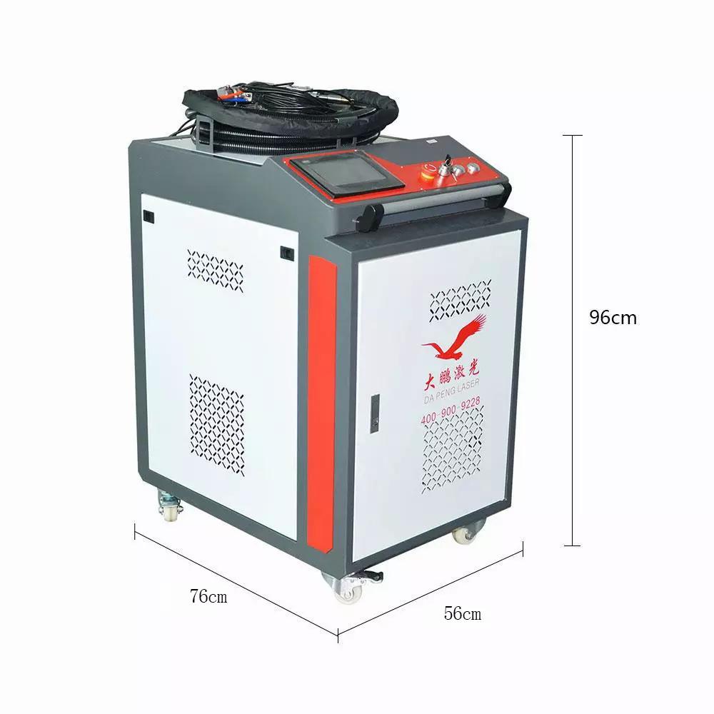
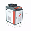
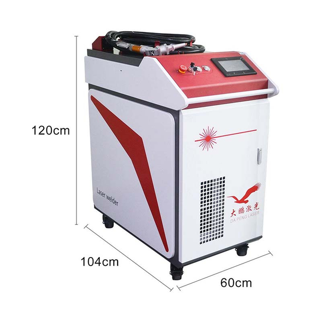
The voltage used by this product is AC 220V, 25A (depending on the power). Connect the power cord to the 220V power supply as shown in the figure.
2. Turn on the air switch of the equipment, and then turn on the emergency stop and the key to turn on the light. After the welding machine is powered on, the cooling fan and the chiller will run automatically (check whether the emergency stop and the key switch are turned on if they are not running). If the chiller is not filled with water, it will alarm. Pour distilled water into the chiller to the green normal area. If the alarm still occurs, please re-run the chiller to ensure that the working area on the chiller display is running.
3. When the chiller is running normally, wait for the chiller to control the water temperature at the set temperature before turning on the laser button, wait for more than 3S, there will be a "di" sound inside the device, then the enable button can be turned on, otherwise it will be invalid .
Laser indicator light: ALARM green ACTIVE red POWER green is normal.
4. Before using the optical fiber hand-held welding machine, it is necessary to inject protective gas (nitrogen or argon), and the equipment is equipped with a protective gas interface (PM8) at the rear, and adjust the gas size according to the welding product (not less than 0.15MPa).
5. Adjust the process parameters in the operating system of the device, click the air valve button to adjust the gas size, close the air valve button after adjusting the gas, and then click "Start" (at this time, the handheld gun has started to swing, and then there is a slight vibration, and the sound of the motor rotating).
6. After completing the above operations, the gun can be used normally.
How to use: clip the alligator clip to the object that needs to be soldered or a metal console that is connected to the object (make sure it is within 3M and not covered by paint). Then gently touch the nozzle of the gun on the welding position, press and hold the trigger button, stretch at a constant speed of about 45° in the front and rear, and release the trigger button to stop the light. (Wire feeding welding does not need to be stretched by itself, the wire will push the gun body to weld by itself)
")
Precautions for use:
Before using the equipment, check whether the protective gas is turned on.
Wear protective glasses when using the device.
The muzzle of the gun must not be aimed at the human body.
Temporarily go away, please turn off the enable.
Precautions for hand-held guns
1. There are no built-in parts available for use, all repairs should be carried out by professionals of our company
Repair, please do not damage the label and open the welding torch head cover, otherwise any damage to the product
Bad the company does not guarantee!
2. Please do not look directly at the light outlet of the welding head. You must wear professional laser protection during the operation.
Eye glasses!
3. Continuous interruption of the power supply will cause damage to the welding control system, please provide continuous and reliable power supply.
source!
4. The external safety lock is 24V high level, please do not connect with the aviation plug GND of the system cable
The case is short-circuited, or the installation is not careful to collide with each other, otherwise the short circuit may burn the power supply
Or the main control board, after the air plug of the gun head is connected, it should be wrapped with insulating tape and insulated!
5. Attention should be paid to the control circuit that the 24V input must supply power to the welding system at the same time, otherwise it may cause signal transmission errors.
6. When installing the QBH, pay attention to the cleanliness of the surrounding environment, and the fan should be turned off.
Flying dust, QBH must be wiped clean before inserting into the gun body, otherwise the collimating lens will be burned!
7. The optical lenses in the welding head are all consumables (collimation, focusing, protective glasses)
piece), if damaged, no warranty: the company promises that the product repair of wearing parts will be returned
In the case of replacement by our company, the product maintenance during the warranty period will be charged for material cost, not
Charge any other fees. Parts that are not wearing parts are not artificially damaged, within the warranty period of this company
The company is responsible for all maintenance costs.

Water machine maintenance:
The chiller level must be in the green area of the tank level indicator.
After adding water for the first time or renewing the water, the air in the pump needs to be exhausted. Operation method: slowly loosen the exhaust plug under the water inlet. Tighten it again when water flows out.
It is recommended to change the water once a quarter (3 months).
Antifreeze in winter: 1. When the new equipment is transported or not used for a long time, the water in the water tank should be drained through sewage. 2. If the ambient temperature at night is lower than 2°C, it is recommended that the customer do not stop the machine or add antifreeze to the car. When the average daily temperature is higher than 5°C, replace the water containing antifreeze with pure water.
Dustproof in summer: Clean the filter screen of the chiller in about a month in summer.
Welding gun system parameters
Attention information
1) Ensure reliable grounding before supplying power.
2) The laser output head is connected with the welding head. Please check the laser output head carefully when using it to prevent dust or other pollution. Please use special lens paper when cleaning the laser output head.
3) If the equipment is not used in accordance with the method specified in this manual, it may be in abnormal working state and cause damage.
4) When replacing the protective glasses, please make sure to protect them well.
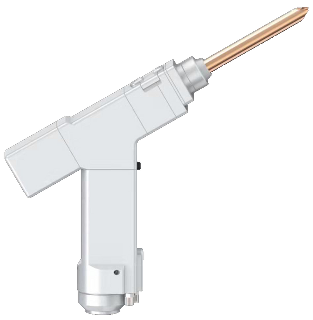
5) Please note: When using for the first time, when the red light cannot come out from the copper mouth, be sure not to emit light
System introduction and use
1 Operation overview and operation guide
The operation panel of SUP series is mainly composed of touch screen and control box. The touch operation interface mainly includes home page, process, setting, monitoring and other parts.
1.1 Touch screen operation main screen
①This interface can see the current process parameters and real-time alarm information.
②In the power-on state, the laser enables and indicates that the red light is ON.
③The safety lock is usually gray, and when the welding head touches the workpiece, it becomes green and can be processed.
④Welding mode selection, the default is continuous. When it is set to spot welding, it can emit light intermittently for spot welding operation, which is convenient to control the spot welding time due to human beings.
1.2 Main screen of process operation
①The process interface includes the process parameters for debugging, click the box to modify, click OK after modification, and then save it in the shortcut process, click import when using (modify-save-import).
②The scanning speed range is 2-6000mm/S, and the scanning width range is 0^5mm. The scanning speed is limited by the scanning width, and the limiting relationship is: 10≤scanning speed/(scanning width*2)≤1000 If the limit is exceeded, it will automatically become the limit value. When the scan width is set to 0, it will not scan (ie point light source) (the most common scan speed: 300mm/S, width 2.5mm).
③The peak power should be less than or equal to the laser power on the parameter page (if the laser power is 1000W, the value should not be higher than 1000).
④ The duty cycle range is 0~100 (default 100, usually does not need to be changed).
⑤ The recommended pulse frequency range is 5-5000Hz (default 2000, usually does not need to be changed).
Process reference (subject to the actual situation, the following is for reference only)
1.3 Setting the main screen of operation
Password 123456
①The laser power is the maximum power of the laser used.
②The default gas delay time is 200ms, and the range is 200ms-3000ms.
③When the light is turned on, it will gradually increase from N1% of the process power to 100%; when the light is turned off, it will gradually increase from 100% of the process power to N2; (as shown in the figure below).
④Wire feeding delay compensation is the wire feeding advance time relative to the light signal, which can be used with the retraction function.
⑤The maximum temperature alarm threshold is 70℃. When the value is set to 0, the temperature alarm will not be detected.
⑥ Scanning correction coefficient range is 0.01~4, coefficient target line width/measurement line width: generally 1.25.
⑦The laser center is offset by -3~3mm, if it is decreased, it will move to the left, and if it is increased, it will move to the right.
⑧ The alarm level signal is the default, and the shielding alarm can be directly changed to the corresponding level detection.
⑨ The duration of spot welding is the light-emitting time after the trigger is pulled, that is, even if the button is released, light will still be emitted according to the time-out (V3.3 version is the above function)
⑩The interval time of spot welding is the light stop time between two spot welding after pulling the trigger button (version V3.3 and above)
This interface displays the status of each detection signal and device information
Click Device Authorization to enter the authorized usage time interface, and after entering the password, the system can be authorized for the usage time.
Maintenance and maintenance of welding torches
1 How to maintain and replace the protective lens:
① The processing technology of laser welding requires regular maintenance of the lens. If the welding effect is found to be poor, check that the protective lens is dirty and replace the protective lens in time.
② Before operation, wash your hands with detergent and dry them, and then wipe your hands again with cotton glued with alcohol.
③ Remove the protective lens compartment cover screws in a relatively dust-free place, pull out the protective lens bracket, do a good job of protection, and check the protective lens (if the surface of the protective lens has obvious burns, it should be replaced directly.)
④ Then check the white power sealing ring under the protective lens. (If the power storage ring has any scratches or deformation, it cannot be used and must be replaced immediately.
⑤ Use a cotton ball dipped in alcohol to wipe the opening of the warehouse and the inside of the warehouse cover, quickly insert the protective mirror bracket into the protective mirror compartment, and tighten the screws.
2 Laser center adjustment method (oblique viewing angle)
When the red light cannot come out of the copper nozzle completely, it needs to be adjusted manually at this time to prevent the copper nozzle from being burned out.
Please note: When using for the first time, when the red light cannot come out from the copper mouth, be sure not to emit light
①, as shown in the figure below, at this time, the red light cannot be seen completely coming out of the copper mouth
②. We need to remove the back cover, you can see four adjustment screws, adjust the center according to the video
③. Finally, to achieve this effect
④. The slight left and right deviation can be set by setting the laser center offset of the panel
Common exception handling
1. Prompt laser/water cooler/air pressure alarm
①If the above alarm occurs without using the alarm signal, please change the alarm level.
②If the above alarm occurs when the alarm signal is used, check whether the alarm of the corresponding device or the level of the alarm signal is set incorrectly.
2. The screen does not light up/click does not respond
① The screen does not light up, if the controller is powered on (the fan is running), check whether the four-core wire between the controller and the screen is connected correctly, and whether the 24V voltage of the 1st pin and the 4th pin is normal
②If the click fails during normal use, check whether the temperature of the whole machine is too high.
③Click can not input, check whether the four-core wire between the controller and the screen is connected correctly, and whether the 2nd and 3rd pins are normal, see 2.1.2 Controller LCD screen for details
④If there is no response when clicking on the newly installed device, it may be that the system version does not match. You can re-flash the program. Please ask our company for the SD card.
3. No light
①The monitoring interface can exclude other alarms. When the welding head touches the workpiece to be processed, the safety lock is displayed in green, and it can be processed at this time. If it is gray, check whether the connection of the safety lock is normal.
That is, check whether all the ready signals are normal
Usually, no light is emitted from the air and the wire is due to a laser fault or a wiring problem. If the air is not fed and the wire is not fed, it may be a problem with the preparation signal. For details, please refer to: 2.1.3 Controller Signal Interface 1
4. Sudden stop of light output during processing
The monitoring interface checks whether the safety lock and other alarms are normal, and also checks whether the temperature exceeds the temperature alarm threshold.
5. Red light bias
Cause Analysis:
1. The external interference source causes the swing motor to work normally, and the red light shifts slowly. Try to avoid sharing a power supply box with equipment such as argon arc welding machines that have a great impact on the power grid. The power supply of the welding head must be effectively grounded , at the same time, isolation transformers, magnetic rings, etc. can be used to eliminate part of the influence
2. The red light shift caused by the new QBH, lens or other replacement parts. When replacing some specific parts, the red light may be inconsistent with the previous one. It can be normalized by software setting or mechanical adjustment.
3. The signal line is broken (only the SUP15S welding head), check the five-core line, this situation is common in the normal processing that the light deviation cannot be adjusted suddenly and the motor has abnormal noise
solution:
1. Software settings (processing of cause 1/2)
Fine-tune by setting the laser center offset in the interface, followed by {1. Setting}-{2. Change the laser center offset value, the negative value is to the right, the positive value is to the left, the latest version can adjust the maximum value +3/-3 }-{3. Go back to the home page, turn off the red light indicator, and then turn on the red light indicator to refresh}. This solution can be fine-tuned left and right. If this method still cannot be adjusted, use mechanical adjustment.
2. Mechanical adjustment (cause 1/2 treatment) (please distinguish between 15S and 20S below)
Before performing mechanical adjustment, be sure to set the center offset to 0, see the three steps of software setting method
3. Disconnection (treatment of cause 3)
Check whether there is an open circuit in the air plug part of the five-core cable, you need to disassemble the air plug
Laser welding machine three-phase power wiring reference
Note: Two-phase or three-phase power depends on the power supply required by the laser and chiller, not the amount of wiring
Warning: Please do not move/install the machine without permission. Before preparing, please contact our after-sales service to provide the power supply definition of the whole machine, and the whole machine must be grounded! !
Wire feeder structure and accessories
one. 1.1 Operating environment and parameters
1.2 Notice information
1) Ensure reliable grounding before supplying power.
2) The wire feed wheel matches the wire warp and corresponds to the wire feed tube
3) The wire feeding tube should not be twisted
2. Installation
1 General definition of circuit wiring
2.1.1 The whole machine provides a three-core aviation plug, which is connected to the three-core aviation plug at the tail of the wire feeder, and provides 220V power supply
2.1.2 The whole machine provides a two-core aviation plug, which is connected to the wire feeding port of the control system to provide wire feeding signals (passive contact, short-circuit wire feeding)
2.2 Installation of the wire reel
1. The welding wire is ordinary welding wire, the common ones are 5KG-30KG can be installed, but do not use flux-cored welding wire
2. Adjust the strength of the roller through the inner hexagon, so that it is not too tight or too loose, and there is no jamming when the wire is fed (usually it is not necessary to adjust)
3. After adjustment, cover the cap
Wire feed roll installation
1. There are two wire feed rollers in total. The two sides are of different models and correspond to different core diameters. Please be sure to install them accordingly.
2. When installing, be sure to clamp the welding wire in the slot and then clamp
3. Installation of wire feeding tube
1. After putting the wire into the wire feeding tube, insert it into the appropriate position. If it is too short, it may cause the phenomenon of jamming, and then tighten the screw.
2. When installing the wire feeding tube, first remove the copper nozzle at one end and match the corresponding copper nozzle
5. Operation panel
1. The numerical value on the home page shows the wire feeding speed, which can be adjusted by the up and down keys. Please keep the running state when using it.
2. Manual wire feeding: After pressing and holding, the wire feeder starts to feed wire, and the manual wire feeding speed depends on the settings in the background
3. Manual retraction: After pressing and holding, the wire feeder starts to retract, and the manual retraction speed depends on the background settings
4. After all settings on the settings page are completed, click Save
5. Set the wire feeding speed of the page as the default wire feeding speed, that is, after changing here, the switch will remain unchanged.
6. Startup delay: not set by default
7; Retraction length and patch length: set according to actual usage
When the wire feeding is stopped, the system will first withdraw a certain distance and then feed the wire a certain distance. This function is mainly used for broken wire
When the wire is still outside at the beginning of each welding, please set the retraction length to be greater than the length of the patch wire.
Pre-sale, in-sale, after-sale service
1. Pre-sales service:
Before signing the contract, the company can provide customers with product samples and technical and price consultation and answers free of charge.
2. In-sale service:
If there is any technical problem during the installation of the product, you can contact the local regional manager at any time.
management or after-sales technical personnel, if you need on-site technical support, you can communicate with the local sales manager
Through the coordination and arrangement of the company.
3. After-sales service:
Customer service response time is within 24 hours within the warranty coverage of the contract term,
Provide efficient technical service support for customers free of charge during the warranty period, and continue to provide after the warranty period expires
Software and hardware support, free upgrade service of software system for life.