The Press Brake Crowning System is a crucial feature in modern press brake machines that ensures consistent bending accuracy by compensating for the natural deflection (bending) of the machine's frame during the bending process. The system corrects this deflection to maintain precise and uniform bending across the entire length of the workpiece.
Functions of the Press Brake Crowning System:
Compensation for Frame Deflection:
During the bending process, the press brake frame and the upper beam can bend under the applied force, especially when bending thick or large metal sheets. This bending or "deflection" can lead to inaccurate bending angles and uneven workpieces.
The crowning system compensates for this deflection by adjusting the position of the lower beam or the tooling, ensuring that the bend remains accurate and consistent across the entire length of the workpiece.
Improved Bending Accuracy:
Crowning systems ensure that the bending force is evenly distributed along the workpiece, preventing excessive or uneven bending at different points of the sheet. This ensures that the final angle is consistent and true to the specifications, even for long or complex bends.
Optimized for V-Dies and Punches:
The crowning system is particularly effective for correcting the deflection that occurs in the V-die or punch area of the press brake, which is where the majority of bending force is concentrated. By adjusting the die or punch positioning dynamically, the crowning system maintains optimal pressure and bending precision.
Automatic and Hydraulic Adjustments:
Hydraulic Crowning Systems: These are the most common types, where hydraulic cylinders adjust the lower beam or other machine components in real-time during the bending operation. Hydraulic crowning systems can compensate for varying material thicknesses and bending forces automatically.
Mechanical Crowning Systems: These use mechanical adjustments, such as screws or rollers, to provide a more manual or semi-automatic solution for frame deflection correction.
Enhanced Machine Efficiency:
By eliminating the need for constant manual adjustments, crowning systems allow for faster and more efficient operation. Operators can focus on other tasks without having to continuously monitor and adjust the machine for deflection.
Crowning also improves the longevity of the machine by reducing the strain and wear on the press brake frame.
Increased Precision in Long Bends:
For press brakes used in large-scale operations or those involving long parts, the crowning system ensures that the full length of the workpiece is bent with uniformity. This is essential for applications such as automotive or aerospace component manufacturing, where high precision is critical.
Reduced Operator Intervention:
Crowning systems help reduce the amount of manual intervention required to achieve consistent results, especially in high-production environments. With automatic adjustments, operators can perform more complex tasks without the need to constantly monitor for deflection issues.
Improved Part Quality:
Reduced Tooling Wear:
Types of Crowning Systems:
Manual Crowning: Requires the operator to adjust the crowning mechanism based on experience and visual inspection.
Mechanical Crowning: Uses mechanical components such as screws or adjustable rollers to correct deflection.
Hydraulic Crowning: Uses hydraulic cylinders to automatically adjust the machine frame or tooling during the bending process for precise deflection compensation.
Advantages of the Press Brake Crowning System:
Increased Precision: Ensures uniform bending across the entire workpiece.
Higher Productivity: Reduces the need for manual adjustments, improving overall machine efficiency.
Enhanced Part Quality: Minimizes the risk of defects and improves the final product.
Less Operator Skill Required: Allows less experienced operators to achieve precise results without the need for constant intervention.
Prolonged Tool and Machine Life: Reduces unnecessary wear on tools and machines, lowering maintenance costs and downtime.

Understanding Components of The Press Brake
Understanding Components of a Press Brake
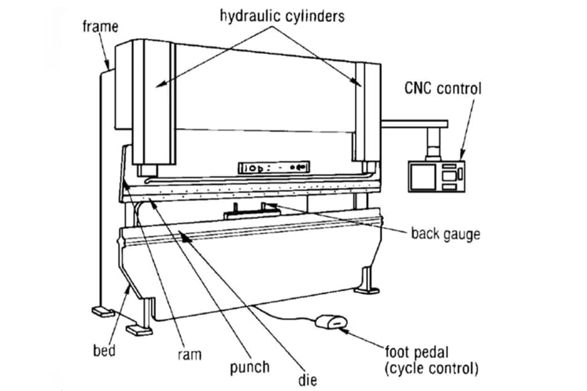
A press brake is a machine tool used for bending sheet metal into various shapes. Below is a detailed explanation of its key components and their functions:
1. Frame
The frame forms the structural foundation of the press brake, providing stability and rigidity during operation. It is crucial for consistent bending results and ensures the machine can withstand the high forces involved without distortion.
Types:
C-Shaped Frame: Compact and suitable for smaller, less powerful machines.
Square Frame: Rigid and designed for heavy-duty operations with larger sheets of metal.
2. Bed
The bed is a flat, stationary surface where the workpiece is placed during bending. It ensures proper alignment of the material and supports the bending process.
3. Ram
The ram is a movable upper component that exerts downward force on the workpiece. It is connected to the punch, directly contacting the metal during the bending process.
4. Punch and Die
Punch: A tool with a specific shape mounted on the upper beam to deform the material during bending.
Die: A complementary tool installed on the lower beam, designed to shape the material into the desired form. Together, the punch and die define the final shape of the bent workpiece.
Understanding Components of a Press Brake
A press brake is a machine tool used for bending sheet metal into various shapes. Below is a detailed explanation of its key components and their functions:
1. Frame
The frame forms the structural foundation of the press brake, providing stability and rigidity during operation. It is crucial for consistent bending results and ensures the machine can withstand the high forces involved without distortion.
Types:
C-Shaped Frame: Compact and suitable for smaller, less powerful machines.
Square Frame: Rigid and designed for heavy-duty operations with larger sheets of metal.
2. Bed
The bed is a flat, stationary surface where the workpiece is placed during bending. It ensures proper alignment of the material and supports the bending process.
3. Ram
The ram is a movable upper component that exerts downward force on the workpiece. It is connected to the punch, directly contacting the metal during the bending process.
4. Punch and Die
Punch: A tool with a specific shape mounted on the upper beam to deform the material during bending.
Die: A complementary tool installed on the lower beam, designed to shape the material into the desired form. Together, the punch and die define the final shape of the bent workpiece.
5. Back Gauge
The back gauge is a precision positioning system located at the rear of the press brake.
6. Control Panel
The control panel is the user interface for operating the press brake.
On CNC press brakes, it allows programming of bending angles, material thickness, and complex sequences, improving precision and efficiency.
7. CNC System
The CNC (Computer Numerical Control) system automates press brake movements, including:
This system ensures high precision and simplifies multi-step operations.
8. Upper and Lower Beams
9. Axes
X-Axis: Controls the back gauge's horizontal movement along the press brake length for flange adjustment.
Y-Axis: Controls the vertical movement of the ram or punch for bending operations.
Z-Axis: Adjusts the back gauge's horizontal positioning along the left and right directions.
R-Axis: Controls the back gauge fingers’ vertical movement for complex or multiple bends.
10. Sheet Support Arms
Mounted at the machine's front, these arms support the workpiece during bending, ensuring alignment and reducing operator strain.
11. Housing Brace
A structural component that connects the two driving cylinders on the upper beam, maintaining machine stability.
12. Foot Pedal
Used by the operator to engage the machine's clutch or initiate bending operations.
13. Crank Shaft
In mechanical press brakes, this component transfers the flywheel's energy to the ram, ensuring efficient energy conversion.
Advanced Terminology and Techniques
Bend Allowance
Bend allowance refers to material deformation or elongation required by forming a specific bending angle. It is calculated according to material thickness, bending radium material characteristics, etc.
Bend Deduction
Bend deduction refers to the difference between the sum of the layout dimensions and the total length of the curved part. It shows the length of the consumed material during the bending process.
Bottom Dead Center
The bottom dead center refers to the lowest point the punch or upper beam arrived at during the downward stroke. This is the position of the brake when it is fully closed into the die.
Braking Capacity
Braking capacity refers to the biggest force or tonnage exerted by bending specific material inside the machine's operation restriction.
Clutch
A clutch is a mechanical device used in the press brake. It can be used to connect or interrupt the power transmission from the motor to the punch. It controls the movement and stop of the ram during the bending process.
Bottom Bending
Bottom bending is a technique in which the upper beam exerts pressure to bend the material into the complete shape of the die. Compared with air bending, the bottom bending keeps the punch and die closer. Thus, more tools will be in contact with metals, and bending can better match the shape of the punch and die. Bottom bending needs more tonnage than air bending.
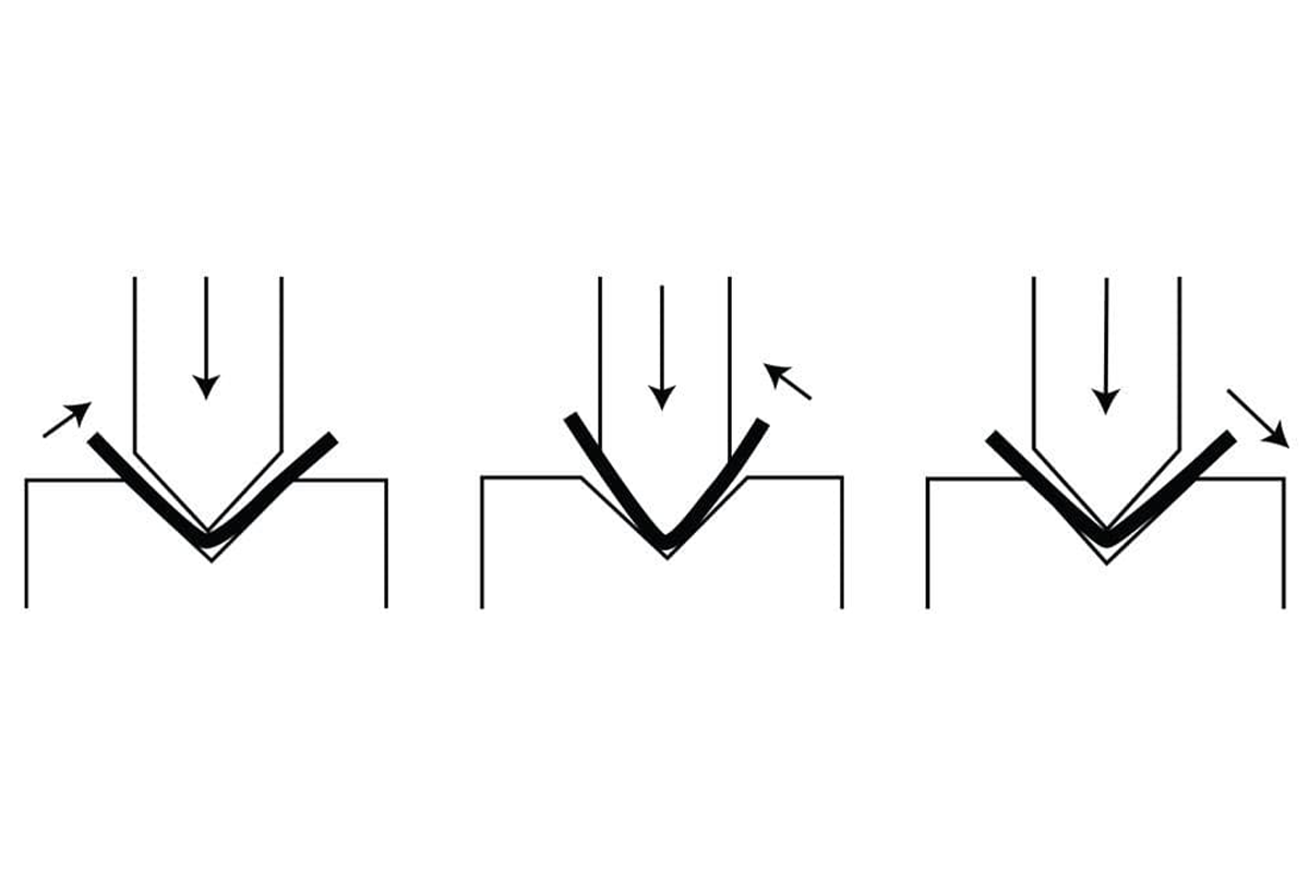
Air Bending
Air bending is the most common bending process used in the press brake industry. It is a bending technique that only uses 3 contact lines to bend the material. The bending occurs at three contact points: the punch nose and the shoulders of the die. The material will not arrive at the bottom thus there will be a more flexible and widespread bending angle.
Compared with other bending methods, air bending gets less in touch with the metal. The bending angle is determined by the depth the punch descends into the die instead of the actual shape of the workpiece itself. Operators can counter springback by slightly overbending the material or applying adjustments based on the metal's elasticity and thickness.
Coining
Coining is a precise bending technology. It presses the material into the die to achieve high precision and correct bending angle. Coining originates from the metal manufacturing process for making coins, which uses extremely high tonnage to compress metal, and makes the metal the same as the die’s angle.
| Bending Technique | Advantages | Challenges | Applications |
| Air Bending | Flexible, low tooling cost | Prone to springback | Automotive, custom fabrication |
| Bottoming | Precise, reduces springback | Requires high force, less flexible | Appliances, structural components |
| Coining | Eliminates springback, high precision | High energy and tooling costs | Aerospace, medical devices |
Spring back
Springback is a trend in that material returns to its original shape after being bent. When the material is bent and released, it will show some spring back, resulting in the bending part being slightly straightened or deformed.
Daylight
Daylight refers to the distance between the upper beam and bottom beam of the press brake when it completely opens without material or tools. It determines the maximum height of material that machines and tools can accommodate.
That is the biggest material size that can be put in the machine. The normal daylight ranges from 12-24 inches. Day light through: a term used to describe the maximum open space a brake can open to given a specific die set.
Deflection Compensation
During the bending process, the upper and lower beams of a press brake may flex under the applied force, leading to inaccuracies in the bend angle and shape. Deflection compensation addresses this issue by ensuring even force distribution.
Modern press brakes are equipped with crowning systems. Adjust their crowning system to compensate for deflection, ensuring accurate bending results.
Deflection
Press brake components (such as the upper beam and bottom beam) will be bent and deflected because of exerting forces during the bending process. Deflection will affect the accuracy and repeatability of the bending operation.
Repeatability
Repeatability is the ability of a press brake to return to an exact position consistently over multiple operations. This feature is critical for producing uniform parts, particularly in high-volume production runs. CNC and hydraulic press brakes achieve high repeatability through advanced systems that maintain consistent ram positioning and movement.
Elasticity
Elasticity is a characteristic that can cause the material to be retrieved from its original shape when influenced by the outer force. The press brake machine tool uses material elasticity to achieve the required bending angle.
Elongation
Elongation refers to the amount of material deformation and stretching during the bending process. It is shown by percent and determined by material characteristics and bending parameters.
Flange
Flange refers to the flat or extended part that material remains unbent during the bending operation. It offers stability and can be regarded as a connecting point of the component or structure.
Gibb Adjustment
Gibb adjustment is a process for adjusting the guiding device. The guiding device is a mechanical components that control the press brake punch and frame gap and stability movement.
Inside Bend Radius
The inside bend radius refers to the radius of curvature of the bending material's inner surface. It is measured by the center line to the innermost point of the bend.
Inside Setback
Inside setback refers to the distance between the material edge and the bending line of the bending inner side. It can ensure the correct positioning of the material and achieve accurate bending.
K Factor
The k factor is the modulus used in press brake bending calculation, which is used to ensure neutral axis position and bend allowance. It takes the material characteristics into consideration like thickness, stretch rate, and stretch tensity.
Mechanical Stop
A mechanical stop is a physical stop or limiter on the press brake back gauge system, which is a terminology used in controlling the material position and ensuring accurate and consistent bending.
Minimum Inside Radius
The minimum inside radius is the minimum radius that can be achieved during the bending operation process. This will not result in acceptable material damage or deformation.
Neutral Axis
The neutral axis is the center axis or line, which keeps constant during bending. When it is stretched and compressed, it almost will not deform.
Outside Setback
Outside setback refers to the distance between the edge of the material and the bend line outside the bend. It ensures correct material position to achieve precise bending.
Pinch Point
The pinch point refers to the area between the upper and bottom beams, where the material will be squeezed during the bending. Keeping the finger and hand away from pinch points is of pivotal importance.
Stroke
Refers to the distance the ram travels during a bending operation, from its highest to lowest point. Stroke length: the maximum open size of the brake press i.e. the distance between the top of the lower beam and the bottom of the upper beam when the brake is fully open and there is no tooling installed. It determines the maximum bending depth that can be achieved.
Tonnage
This will be the maximum force that the press brake can exert on the workpiece. This measurement is critical for determining the machine’s capacity to bend specific materials and thicknesses.
To calculate the required tonnage, press brake operators must consider the material’s thickness, tensile strength, and the desired bend radius. For example, bending thicker steel requires more tonnage to avoid excessive deformation or even damage to the machine.
Swing up Finger
Back gauge fingers or stops can be swung upward and retracted, allowing larger or wider components that bend beyond the normal back gauge range.
Tandem
Two or more press brakes controlled by the same controller which are used to bend extremely large parts.
Tensile Strength
Tensile strength refers to the biggest stretch force that the material can be bent before broken or invalid. This is the factor to be considered when choosing the bending material.
Throat
Throat refers to the maximum depth distance ranging from the center line of the bottom beam to the frame. The depth of the press brake before the vertical supports limits flange length. It determines the biggest depth of the material that can be bent across its entire width. Most press brakes are only constrained by the throat of a brake around the driving cylinders.
Top Dead Center
The top dead center is the highest point arrived by the punch or upper beam of the press brake during the upper stroke. This is the position of the brake when it is fully closed into the die.