Electro-Hydraulic Proportional System for 30T–50T Press Brake
Introduction:
The electro-hydraulic proportional system is an advanced hydraulic control system designed specifically for 30T–50T press brakes. It integrates cutting-edge technology to ensure high precision, responsiveness, and reliability, making it ideal for modern sheet metal bending applications.

Product Features:
Fast Positioning: Adopts high-response proportional servo valve with a response frequency of 80–100Hz.
Precision: Positioning accuracy reaches 0.01mm.
Compact Design: Integrated high-pressure filter.
Functionality: Built-in hydraulic deflection compensation function.
Feedback: Equipped with an LVDT displacement sensor for enhanced accuracy control.
Specifications and Configuration Table:
| Configuration | 30T–50T | 63T | 110T | 125T–170T | 200T–250T | 300T–320T |
| Normally Open Valve | PV32 | PV50 | PV50 | PV50 | PV50 | PV50 |
| Normally Closed Valve | SVF–32–21C | SVF–40–21C | SVF–40–21C | SVF–40–21C | SVF–50–21C | SVF–50–21C |
| Oil Pump | 10cc | 16cc | 20cc | 25cc | 32cc | 40cc |
| Servo Valve | NG6 | NG6 | NG6 | NG6 | NG6 | NG6 |
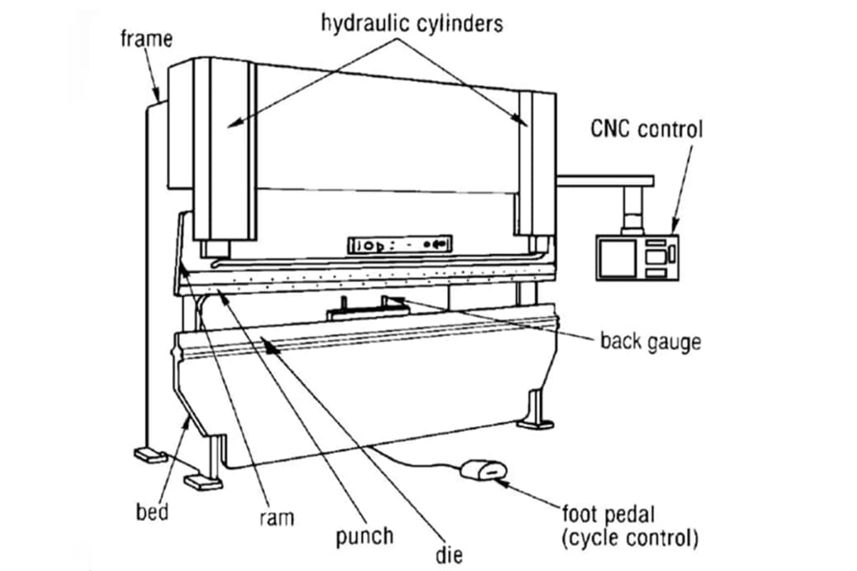
Understanding Components of The Press Brake
Frame
The structural foundation of the press brake, supporting all other components. It provides stability and rigidity during operation, ensuring consistent bending results. For example, a robust frame ensures that the machine can withstand the high forces involved in bending thick metal without distortion.
Frames come in two primary configurations: C-shaped and square. C-shaped frames are commonly used in smaller or less powerful machines, offering a compact design and sufficient support for lighter bending tasks. Square frames, on the other hand, are typically found in larger, more powerful press brakes designed for heavy-duty operations. They provide greater rigidity and are better suited for handling larger sheets of metal and higher bending forces.
Bed
It is a fixed, flat surface used for the bending machine to lie the workpiece. It supports and ensures the bending process is correct and aligned. Bed plate: the stabilizing and supporting foundation of any brake press.
Ram
Ram is on the upper part of the press brake, which can be moved downward to exert bending force on the workpiece. It is connected to the punch and directly touches and helps form the metal.
Die
The die is a tooling and part with a specific shape used in the press brake and designed for shaping and forming the material. It is usually installed on the bottom beam.
Punch
The punch is also the tool and part with specific shapes used in the bending process for making materials to form. It is usually installed on the upper beam.
Back Gauge
The back gauge is the mechanism and CNC controller installed on the rear of the press brake bending area. It is composed of the fingers and stops and is designed to position the bending material precisely, which can ensure a consistent and accurate bending operation.
Back Gauge Origin
The back gauge origin is the reference point measured on the back gauge system. It ensures the starting location of the back gauge during the bending operation. A preset position for the back gauge, forms the center of the set V opening.
Control Panel
The interface used to operate the press brake, adjust settings, and monitor performance. On CNC press brakes, the control panel enables highly precise programming for complex bending sequences. CNC control panels allow operators to program bending angles, material thickness, and even manage multiple operations in a single cycle, which can greatly improve efficiency.
CNC System
CNC is the abbreviation of the computer numerical control. It refers to a control system utilizing computer programs to control the machine movement automatically, which includes back gauge, ram, and other axes.
Upper Beam
The upper beam is a movable beam or punch of the press brake, which can exert pressure on the material to perform bending. It fixes the punch and exerts the pressure via vertical movement.
Lower Beam
The lower beam plays a vital role in press brake fixing, which can offer support for die or bottom tools. When the upper beam or punch moves vertically to exert bending operations, it will keep stable.
X-axis
The X-axis refers to a horizontal axis that can control the back gauge moving along the press brake length. The operator controls the back-and-forth movement of the back gauge, thus ensuring the flange length.
Y-axis
The y-axis is a vertical axis that can control the movement of the press brake punch or upper beam. The ram's vertical movement is called the Y axis. If the press brake is equipped with two independent cylinders, the CNC press brake can directly control each side of the cylinder. The left side of the ram is Y1, and the right side of the ram is Y2.
Z axis
The z-axis refers to the horizontal axis that moves or stops along the left and right locations. The Z-axis is used to measure the location and movement of the back gauge.
R axis
The R axis is used to control the back gauge finger's vertical movement or stop. It can bend complex shapes or achieve multiple bends. The back gauge vertical movement is the R axis, which can be controlled on some CNC press brakes. R1 and R2 refer to the up and down movement of the left and right back gauges.
Sheet Support Arms
These sheet support arms are extended parts installed on the front of the machine, which are used to support the workpiece during bending. Sometimes, they can measure the workpiece.
Housing Brace
A structural component of the upper beam which holds the two driving cylinders of a press brake together.
Foot Pedal
The part of a mechanical press brake that is used by the operator to engage the clutch.
Crank Shaft
The component of a mechanical press brake which transfers the energy of the flywheel to the ram.
Features and Benefits:
High Responsiveness:
Precision Control:
Positioning accuracy up to 0.01mm, enabling precise bending angles and consistent results.
Includes an LVDT displacement sensor for real-time feedback and enhanced control.
Compact Design:
Hydraulic Deflection Compensation:
Energy Efficiency:
Functions:
Positioning and Bending:
Automatic Deflection Compensation:
Load Control:
Real-Time Feedback:
Safety and Reliability: